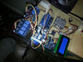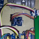
 I’ve been working on the control units for the dashboard etc, and I have picked up an ADXL335 3 way accelerometer from SparkFun to include in the data logging statistics. It took a little while, but eventually I have it working how I want, although not all the code is on the Nano, the G-meter is working.
If you’ve come to this page because you want to get your ADXL335 working, read on, I’ll save you some headaches and give you some code to get it all working. The ADXL335 is very sensitive so try and mount it on something flat and stable and that you can also move obviously! Sparkfun offers a library to download, and this includes a calibration program that you will need, and is important to measure the output at your zero position.
First you need to connect your breakout board to your Arduino. I won’t tell you how to suck eggs, but +5v goes to vcc, Gnd goes to Gnd and analogue pins 0, 1, 2 go to pins x, y, z in that order.
You can do this without downloading the library using my sketch below but commenting these 3 lines out and commenting the three after.
You may need to go find the streaming.h library btw…!
[code]
xG = xVoltage ;
yG = yVoltage ;
zG = zVoltage ;
// xG = (xVoltage – 1.24) / .30;
// yG = (yVoltage – 1.27) / .30;
// zG = (zVoltage – 1.53) / .30;
[/code]
Load the code onto your Arduino and run it. Open the serial monitor and leave the ADXL355 flat on the surface and take a note of the values being shown. These are your zero values and you can add them back into the code, replacing the values I have provided of 1.24, 1.27 and 1.53. Comment out the first 3 lines remove the comment on the next three lines and we are ready to go.
The figures we worked out are to show a zero value, the division by .30 is because the spec sheet on the ADXL355 shows that it increases or decreases voltage by 30mV per G, so the resulting voltage divided by .30 gives us a fairly accurate G measurement.
[code]
/*
This is an example script for use with Arduino and the Grove
ADXL335.
The output when tuned will display G force along 3 axis.
Tim Russell
http://www.russellweb.eu/
*/
#include
const int xPin = 0;
const int yPin = 1;
const int zPin = 2;
float xG, yG, zG;
float xVoltage, yVoltage, zVoltage;
float x, y, z;
void setup(){
Serial.begin(115200);
}
void loop()
{
getGforce();
Serial << "x: "; if (xG >= 0) {
Serial << "+" << xG ;
}else{
Serial << xG ;
}
Serial << "\t y: "; if (yG >= 0) {
Serial << "+" << yG ;
}else{
Serial << yG ;
}
Serial << "\t z: "; if (yG >= 0) {
Serial << "+" << yG ;
}else{
Serial << yG ;
}
Serial << "\r\n";
delay(500);
}
void getGforce()
{
x = analogRead(xPin);
y = analogRead(yPin);
z = analogRead(zPin);
xVoltage = (float)x*5/1024;
yVoltage = (float)y*5/1024;
zVoltage = (float)z*5/1024;
// xG = xVoltage ;
// yG = yVoltage ;
// zG = zVoltage ;
xG = (xVoltage – 1.24) / .30;
yG = (yVoltage – 1.27) / .30;
zG = (zVoltage – 1.53) / .30;
}
[/code]
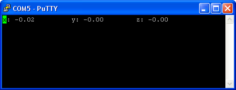
Using the serial monitor with the Arduino program the information will scroll, but if you use PuTTY you can change the carriage return and line feed (“\r\n”) to just a carriage return (“\r”), this will give a single line view in the PuTTY window like this.

